Output Devices
Group assignment:
Measure the power consumption of an output device
Individual assignment:
Add an output device to a microcontroller board you’ve designed, and program it to do something
output Devices
An output device is any piece of computer hardware equipment which converts information into human-readable form. It can be text, graphics, tactile, audio, and video. Some of the output devices are Visual Display Units (VDU) i.e. a Monitor, Printer, Graphic Output devices, Plotters, Speakers etc. A new type of Output device is been developed these days, known as Speech synthesizer, a mechanism attached to the computer which produces verbal output sounding almost like human speeches. Some examples of output devices are given below: wiki
- Monitor
- Printer
- Speaker
- Headphones
- Projecter
- GPS
- Sound Card
- Video Card
- OMR
- Braille reader
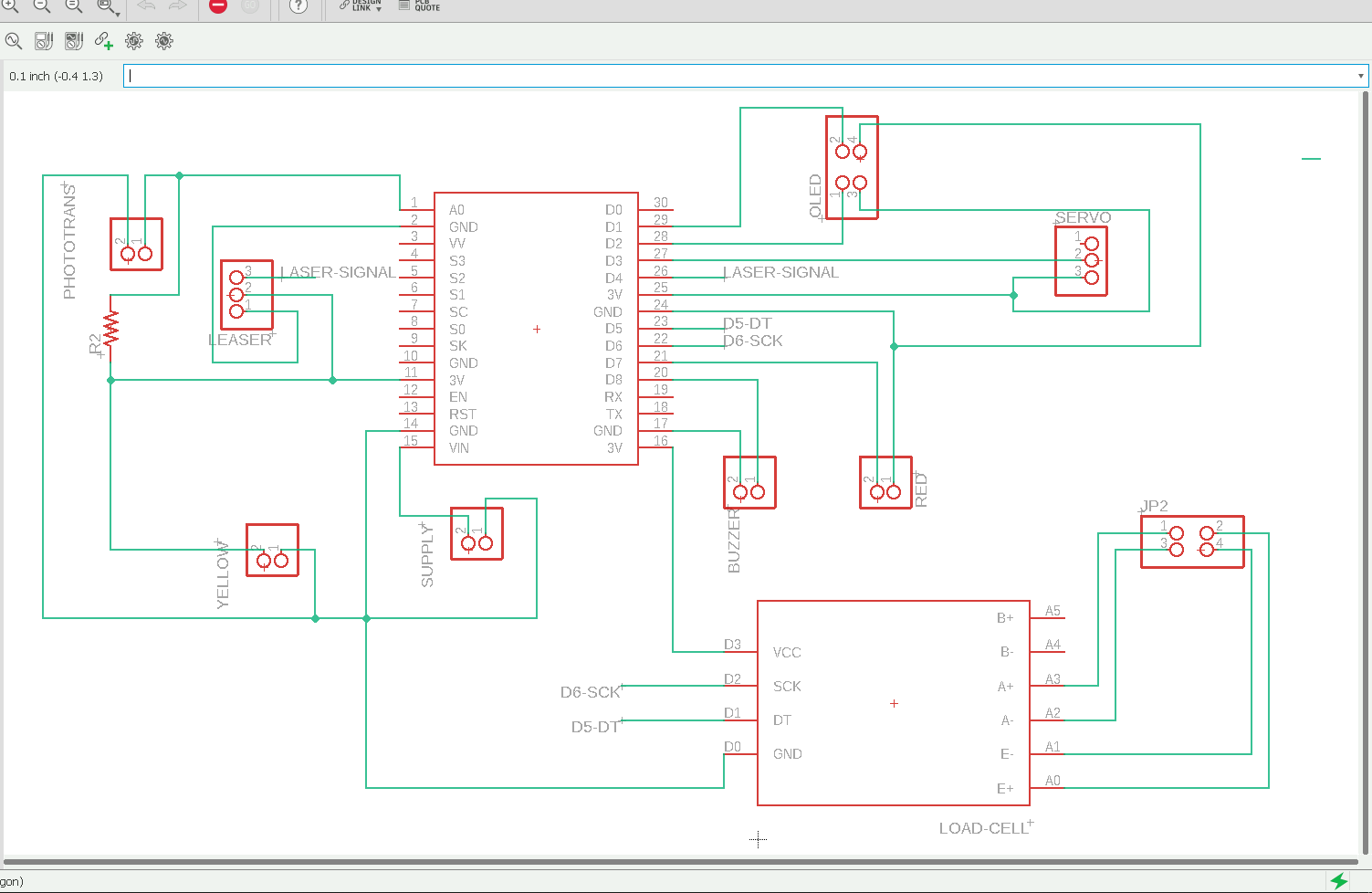
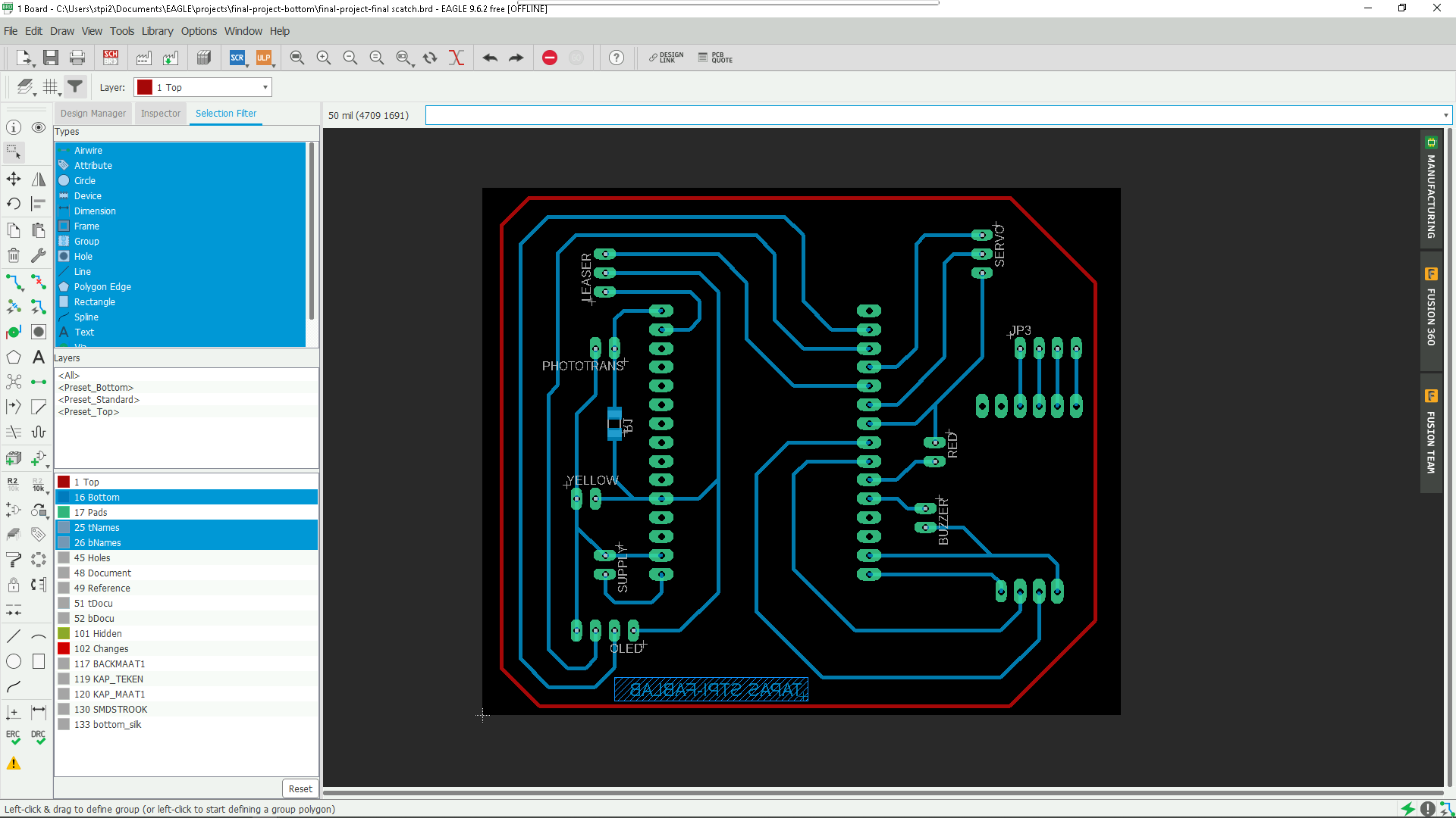
In my final project i have to use output device OLED for display,LOADCELL for wight measurement,
Servo Motor to block the drip flowThis week we went over output devices.
- Display Unit (LCD or OLED)
- Servo motor
- Load Cell
- BUZZER
- laser diode
Display Unit (LCD or OLED):-
Liquid Crystal Display
Liquid crystal display is a combination of two states of matter, the solid and the liquid. LCD uses a liquid crystal to produce a visible image. Liquid crystal displays are super-thin technology display screens that are generally used in laptop computer screens, TVs, cell phones and portable video games.
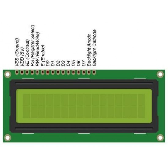
The one that I have is the 16x2 LCD. A 16x2 LCD means it can display 16 characters per line and there are 2 such lines. In this LCD each character is displayed in 5x7 pixel matrix. This LCD has two registers, namely, Command and Data. The command register stores the command instructions given to the LCD. A command is an instruction given to LCD to do a predefined task like initializing it, clearing its screen, setting the cursor position, controlling display etc. The data register stores the data to be displayed on the LCD. The data is the ASCII value of the character to be displayed on the LCD. Click to learn more about internal structure of a LCD.You can download the datasheet from Here.Here is the datasheet

Data-sheet of LCM-S01602DTR/M
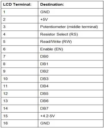
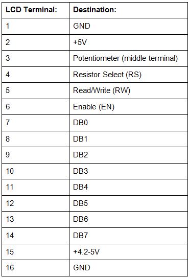
The LCD module has 16 pins numbered from 1 to 16.Pin 1, 2 ; 3 are for power supply and adjusting the contrast with Pin 1 acting as GND and Pin 2 as VCC.Voltage at Pin 3 defines the contrast of the LCD. By connecting a potentiometer to Pin 3,we can control the contrast according to the final environment into which the LCD is put in use.;
Pin 4 is the "Register select" pin which defines if the incoming data(on Pin 7 to 14) is an instruction or characters to be displayed. Making this pin high makes the LCD to read the incoming data as characters to be displayed and does accordingly. Making this pin low makes the LCD to read the incoming data(on Pin 7 to 14) as instructions. The instruction can be to set the cursor to a specific location, clear the display, turn off the display etc. This pin has to be connected to the MCU.
Pin 5 is the "Read/Write" pin which selects the mode whether we will write to the LCD or read from the LCD. A high state sets the LCD to "Read" mode and a low to "Write" mode. If nothing is to be read from an LCD screen, this pin can be permanently set to low and can be connected to GND.
PIN 6 is the "Enable" pin which triggers the clock inside the LCD module so as to execute the instructions given to the LCD. The instructions/displaying of characters will be executed when this pin turns from low to high.This pin has to be connected to the microcontroller which will take control of generating clock signals.
PIN 7 to 14 are the 8 data pins. The LCD module can work in 4/8 bits operation. All the 8 pins have to be connected to the microcontroller for transferring 8 bits of data at a time. For carrying out a four bit operation, data pins D4, D5, D6 & D7 (PIN 11, 12 ,13 & 14 respectively) are to be used.
Pin 15 & 16 are not to be connected and are relevant only for LCD's with backlight with the pins acting as the anode and cathode for the LED backlight.
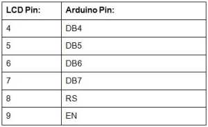
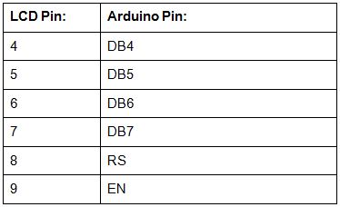
Connection between Arduino and LCD with potentiometer
LCD has a total of 16 pins. Here’s what each pin is designed to do:
Pins 1 and 16: These are your power and ground.
Pin 3: Used to adjust the brightness of the LCD.
Pins 4-6: Used to operate the LCD.
Pins 7-14: Used as data lines.
Pins 15-16: Used to power the LCD’s backlight.
Interface an LCD with an Arduino
Your potentiometer should connect via its two outer terminals to 5V and to GND. The middle terminal should connect to pin 3 on your LCD. By connecting it this way, your potentiometer can now be rotated to control how bright the backlight of LCD.
Before wiring the LCD screen to your Arduino board we suggest to solder a pin header strip to the
14 (or 16) pin count connector of the LCD screen,

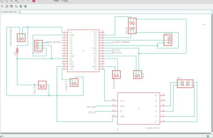
Here is the schematic connection between Arduino uno and LCD
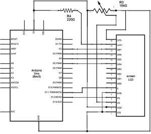


In LCD there are 16 pin but here in above i have been using 12 no of pin,and the display panel is small,
input power it needs +5v . To over come these problem my instructor suggested me to use OLED.In my final project the i have to use Nodemcu8266 hence i have use OLED with Nodemcu8266
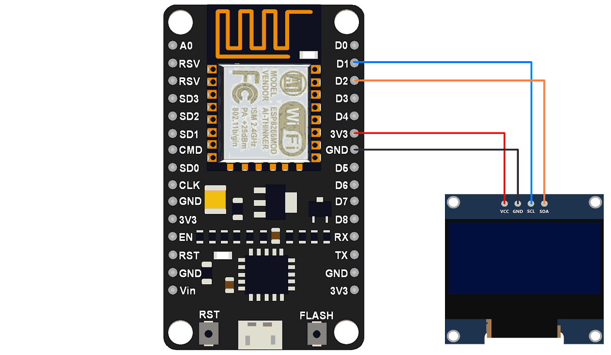
1.3” I2C OLED
OLED’s hold an advantage over LCDs and TFTs because they don’t need backlight and consumes very little power.There are two kinds of 1.3” OLED that you’ll find: SPI and I2C. The SPI OLED has 7 pins while the I2C OLED has only four pins. This tutorial will primarily feature the I2C OLED because some users have trouble using it with non-Arduino boards.
The 1.3” OLED display uses either 3.3V or 5V. Here are the rest of its specifications:
- Diagonal Screen Size:1.3"
- Number of Pixels:128 x 64
- Color Depth:Monochrome (Write)
- Dimension:35.4 x33.5x 4.3 mm
- Power: 0.06W Max
- Viewing Angle: >160 Degree
- Duty:1/32
- Brightness ( cd/m2):150 (Typ) @ 5V
- Interface: I2C
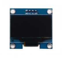

display module uses I2C interface for communication, We must first understand the I2C Protocol.
I2C is a communication method which only uses 4 pins. In this Protocol, multiple Masters (Microcontrollers) can be connected to multiple slaves (Sensors)
using 4 pins: VCC, GND, SDA and SCL.
There are a couple of libraries that needs to be installed.
- Wire.h
- SH1106.h

#include <Wire.h>
#include "SH1106.h"

int a = 0;
int count=0;
int laserpin = D4;
int drip=0;

#define OLED_RESET -1

SH1106 display(0x3c, D2, D1);

void setup()
{
pinMode (laserpin,OUTPUT);
pinMode(A0,INPUT);
Serial.begin(115200);
digitalWrite(laserpin,HIGH);
display.init();
display.flipScreenVertically();
}

void loop() {
  // put your main code here, to run repeatedly

  int x ;
  x=analogRead(A0);
   if (x>=100 && a==0)
   {
    a=1;
   }
   else if (x<100 && a==1)
        {
          a=0;
          drip++;
        }
  Serial.println(x);
  display.setFont(ArialMT_Plain_16);
  display.setTextAlignment(TEXT_ALIGN_LEFT);
  //display.drawString(10, 0, "Drip");
  display.drawString(0, 0, "Dripcount:"+String(drip));
  delay (1);
  display.display();
  display.clear();

}
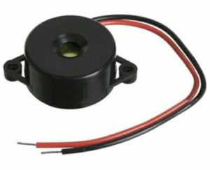
Piezo buzzers
Piezo buzzers are simple devices that can generate basic beeps and tones. They work by using a piezo crystal, a special material that changes shape when voltage is applied to it. If the crystal pushes against a diaphragm, like a tiny speaker cone, it can generate a pressure wave which the human ear picks up as sound.
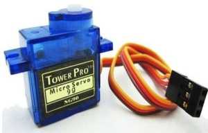
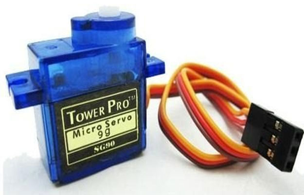
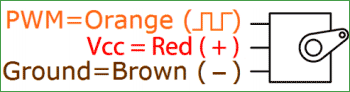
servo motor
A servo motor is a type of motor that can rotate with great precision. Normally this type of motor consists of a control circuit that provides feedback on the current position of the motor shaft, this feedback allows the servo motors to rotate with great precision. If you want to rotate an object at some specific angles or distance, then you use a servo motor. It is just made up of a simple motor which runs through a servo mechanism. If motor is powered by a DC power supply then it is called DC servo motor, and if it is AC-powered motor then it is called AC servo motor. For this tutorial, we will be discussing only about the DC servo motor working. Apart from these major classifications, there are many other types of servo motors based on the type of gear arrangement and operating characteristics. A servo motor usually comes with a gear arrangement that allows us to get a very high torque servo motor in small and lightweight packages. Due to these features, they are being used in many applications like toy car, RC helicopters and planes, Robotics, etc.

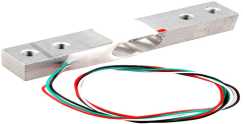
Load Cell
A load cell is a type of transducer, specifically a force transducer. It converts a force such as tension, compression, pressure, or torque into an electrical signal that can be measured and standardized. As the force applied to the load cell increases, the electrical signal changes proportionally. Load cells are used to measure weight.
Load cells generally consist of a spring element on which strain gauges have been placed. The spring element is usually made of steel or aluminum. That means it is very sturdy, but also minimally elastic. As the name “spring element” suggests, the steel is slightly deformed under load, but then returns to its starting position, responding elastically to every load. These extremely small changes can be acquired with strain gauges. Then finally the deformation of the strain gauge is interpreted by analysis electronics to determine the weight.
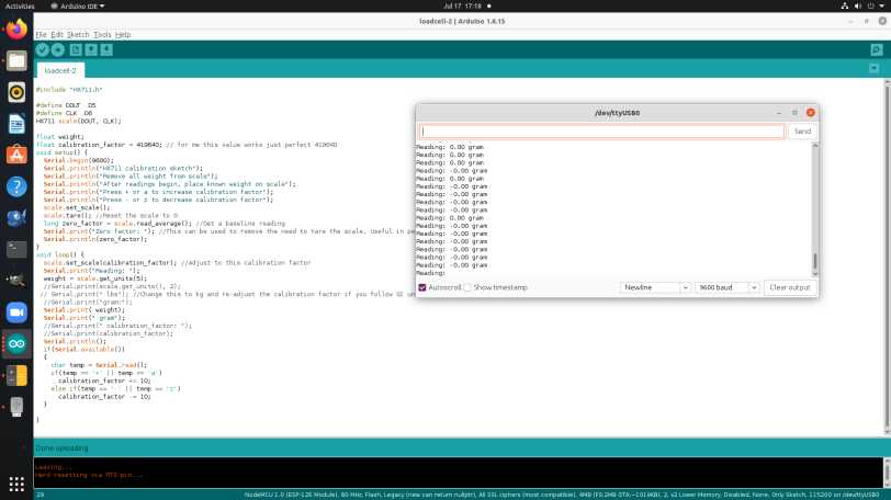
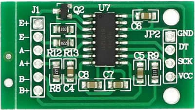
The HX711 Dual-Channel 24 Bit Precision A/D weight Pressure Sensor Load Cell Amplifier and ADC Module is a small breakout board for the HX711 IC that allows you to easily read load cells to measure weight. By connecting the module to your microcontroller you will be able to read the changes in the resistance of the load cell and with some calibration. You’ll be able to get very accurate weight measurements.
This can be handy for creating your own industrial scale, process control, or simple presence detection. The HX711 Weighing Sensor uses a two-wire interface (Clock and Data) for communication. Any microcontroller’s GPIO pins should work making it easy to read data from the HX711.
Each color corresponds to the conventional color coding of load cells :
1. Red (Excitation+ or VCC).
2. Black (Excitation- or GND).
3. White (Amplifier+, Signal+, or Output+).
4. Green (A-, S-, or O-).
5. Yellow (Shield).


Click to download the file :
Resource
- https://deepbluembedded.com/esp32-lcd-display-16x2-without-i2c-arduino/
- https://www.circuitschools.com/interfacing-16x2-lcd-module-with-esp32-with-and-without-i2c/
- https://www.learnrobotics.org/blog/oled-display-arduino/
- https://github.com/rene-mt/esp8266-oled-sh1106
- https://lastminuteengineers.com/oled-display-esp8266-tutorial/
- https://circuits4you.com/2019/01/12/esp8266-servo-motor-control/
- https://www.engineersgarage.com/servo-motor-with-nodemcu-web-control/
- https://www.tomsonelectronics.com/blogs/news/servo-motor-interfacing-with-nodemcu
- https://how2electronics.com/iot-weighing-scale-hx711-load-cell-esp8266/
- https://iotdesignpro.com/projects/smart-weighing-machine-for-remote-weight-measurement
- https://www.electroniclinic.com/diy-iot-weighing-scale-using-hx711-load-cell-nodemcu-esp8266-arduino/
- Display Unit (LCD or OLED)
- Servo motor
- Load Cell
- BUZZER
- laser diode
Display Unit (LCD or OLED):-
Liquid Crystal Display
Liquid crystal display is a combination of two states of matter, the solid and the liquid. LCD uses a liquid crystal to produce a visible image. Liquid crystal displays are super-thin technology display screens that are generally used in laptop computer screens, TVs, cell phones and portable video games.
The one that I have is the 16x2 LCD. A 16x2 LCD means it can display 16 characters per line and there are 2 such lines. In this LCD each character is displayed in 5x7 pixel matrix. This LCD has two registers, namely, Command and Data. The command register stores the command instructions given to the LCD. A command is an instruction given to LCD to do a predefined task like initializing it, clearing its screen, setting the cursor position, controlling display etc. The data register stores the data to be displayed on the LCD. The data is the ASCII value of the character to be displayed on the LCD. Click to learn more about internal structure of a LCD.You can download the datasheet from Here.Here is the datasheet

Data-sheet of LCM-S01602DTR/M
The LCD module has 16 pins numbered from 1 to 16.Pin 1, 2 ; 3 are for power supply and adjusting the contrast with Pin 1 acting as GND and Pin 2 as VCC.Voltage at Pin 3 defines the contrast of the LCD. By connecting a potentiometer to Pin 3,we can control the contrast according to the final environment into which the LCD is put in use.;
Pin 4 is the "Register select" pin which defines if the incoming data(on Pin 7 to 14) is an instruction or characters to be displayed. Making this pin high makes the LCD to read the incoming data as characters to be displayed and does accordingly. Making this pin low makes the LCD to read the incoming data(on Pin 7 to 14) as instructions. The instruction can be to set the cursor to a specific location, clear the display, turn off the display etc. This pin has to be connected to the MCU.
Pin 5 is the "Read/Write" pin which selects the mode whether we will write to the LCD or read from the LCD. A high state sets the LCD to "Read" mode and a low to "Write" mode. If nothing is to be read from an LCD screen, this pin can be permanently set to low and can be connected to GND.
PIN 6 is the "Enable" pin which triggers the clock inside the LCD module so as to execute the instructions given to the LCD. The instructions/displaying of characters will be executed when this pin turns from low to high.This pin has to be connected to the microcontroller which will take control of generating clock signals.
PIN 7 to 14 are the 8 data pins. The LCD module can work in 4/8 bits operation. All the 8 pins have to be connected to the microcontroller for transferring 8 bits of data at a time. For carrying out a four bit operation, data pins D4, D5, D6 & D7 (PIN 11, 12 ,13 & 14 respectively) are to be used.
Pin 15 & 16 are not to be connected and are relevant only for LCD's with backlight with the pins acting as the anode and cathode for the LED backlight.
Connection between Arduino and LCD with potentiometer
LCD has a total of 16 pins. Here’s what each pin is designed to do:
Pins 1 and 16: These are your power and ground.
Pin 3: Used to adjust the brightness of the LCD.
Pins 4-6: Used to operate the LCD.
Pins 7-14: Used as data lines.
Pins 15-16: Used to power the LCD’s backlight.
Interface an LCD with an Arduino
Your potentiometer should connect via its two outer terminals to 5V and to GND. The middle terminal should connect to pin 3 on your LCD. By connecting it this way, your potentiometer can now be rotated to control how bright the backlight of LCD.
Before wiring the LCD screen to your Arduino board we suggest to solder a pin header strip to the 14 (or 16) pin count connector of the LCD screen,
Here is the schematic connection between Arduino uno and LCD

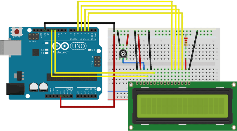
In LCD there are 16 pin but here in above i have been using 12 no of pin,and the display panel is small, input power it needs +5v . To over come these problem my instructor suggested me to use OLED.In my final project the i have to use Nodemcu8266 hence i have use OLED with Nodemcu8266
1.3” I2C OLED
OLED’s hold an advantage over LCDs and TFTs because they don’t need backlight and consumes very little power.There are two kinds of 1.3” OLED that you’ll find: SPI and I2C. The SPI OLED has 7 pins while the I2C OLED has only four pins. This tutorial will primarily feature the I2C OLED because some users have trouble using it with non-Arduino boards.
The 1.3” OLED display uses either 3.3V or 5V. Here are the rest of its specifications:
- Diagonal Screen Size:1.3"
- Number of Pixels:128 x 64
- Color Depth:Monochrome (Write)
- Dimension:35.4 x33.5x 4.3 mm
- Power: 0.06W Max
- Viewing Angle: >160 Degree
- Duty:1/32
- Brightness ( cd/m2):150 (Typ) @ 5V
- Interface: I2C

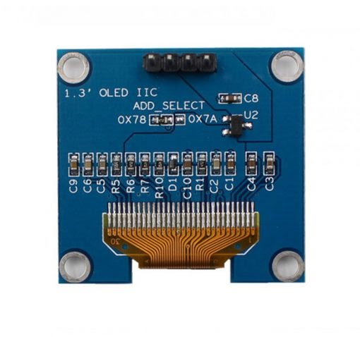
display module uses I2C interface for communication, We must first understand the I2C Protocol. I2C is a communication method which only uses 4 pins. In this Protocol, multiple Masters (Microcontrollers) can be connected to multiple slaves (Sensors) using 4 pins: VCC, GND, SDA and SCL.
There are a couple of libraries that needs to be installed.
- Wire.h
- SH1106.h
#include <Wire.h>
#include "SH1106.h"
int a = 0;
int count=0;
int laserpin = D4;
int drip=0;
#define OLED_RESET -1
SH1106 display(0x3c, D2, D1);
void setup()
{
pinMode (laserpin,OUTPUT);
pinMode(A0,INPUT);
Serial.begin(115200);
digitalWrite(laserpin,HIGH);
display.init();
display.flipScreenVertically();
}
void loop() {
// put your main code here, to run repeatedly
int x ;
x=analogRead(A0);
if (x>=100 && a==0)
{
a=1;
}
else if (x<100 && a==1)
{
a=0;
drip++;
}
Serial.println(x);
display.setFont(ArialMT_Plain_16);
display.setTextAlignment(TEXT_ALIGN_LEFT);
//display.drawString(10, 0, "Drip");
display.drawString(0, 0, "Dripcount:"+String(drip));
delay (1);
display.display();
display.clear();
}
Piezo buzzers
Piezo buzzers are simple devices that can generate basic beeps and tones. They work by using a piezo crystal, a special material that changes shape when voltage is applied to it. If the crystal pushes against a diaphragm, like a tiny speaker cone, it can generate a pressure wave which the human ear picks up as sound.

servo motor
A servo motor is a type of motor that can rotate with great precision. Normally this type of motor consists of a control circuit that provides feedback on the current position of the motor shaft, this feedback allows the servo motors to rotate with great precision. If you want to rotate an object at some specific angles or distance, then you use a servo motor. It is just made up of a simple motor which runs through a servo mechanism. If motor is powered by a DC power supply then it is called DC servo motor, and if it is AC-powered motor then it is called AC servo motor. For this tutorial, we will be discussing only about the DC servo motor working. Apart from these major classifications, there are many other types of servo motors based on the type of gear arrangement and operating characteristics. A servo motor usually comes with a gear arrangement that allows us to get a very high torque servo motor in small and lightweight packages. Due to these features, they are being used in many applications like toy car, RC helicopters and planes, Robotics, etc.
Load Cell
A load cell is a type of transducer, specifically a force transducer. It converts a force such as tension, compression, pressure, or torque into an electrical signal that can be measured and standardized. As the force applied to the load cell increases, the electrical signal changes proportionally. Load cells are used to measure weight.
Load cells generally consist of a spring element on which strain gauges have been placed. The spring element is usually made of steel or aluminum. That means it is very sturdy, but also minimally elastic. As the name “spring element” suggests, the steel is slightly deformed under load, but then returns to its starting position, responding elastically to every load. These extremely small changes can be acquired with strain gauges. Then finally the deformation of the strain gauge is interpreted by analysis electronics to determine the weight.

The HX711 Dual-Channel 24 Bit Precision A/D weight Pressure Sensor Load Cell Amplifier and ADC Module is a small breakout board for the HX711 IC that allows you to easily read load cells to measure weight. By connecting the module to your microcontroller you will be able to read the changes in the resistance of the load cell and with some calibration. You’ll be able to get very accurate weight measurements.
This can be handy for creating your own industrial scale, process control, or simple presence detection. The HX711 Weighing Sensor uses a two-wire interface (Clock and Data) for communication. Any microcontroller’s GPIO pins should work making it easy to read data from the HX711.
Each color corresponds to the conventional color coding of load cells :
1. Red (Excitation+ or VCC).
2. Black (Excitation- or GND).
3. White (Amplifier+, Signal+, or Output+).
4. Green (A-, S-, or O-).
5. Yellow (Shield).


Click to download the file :
Resource
- https://deepbluembedded.com/esp32-lcd-display-16x2-without-i2c-arduino/
- https://www.circuitschools.com/interfacing-16x2-lcd-module-with-esp32-with-and-without-i2c/
- https://www.learnrobotics.org/blog/oled-display-arduino/
- https://github.com/rene-mt/esp8266-oled-sh1106
- https://lastminuteengineers.com/oled-display-esp8266-tutorial/
- https://circuits4you.com/2019/01/12/esp8266-servo-motor-control/
- https://www.engineersgarage.com/servo-motor-with-nodemcu-web-control/
- https://www.tomsonelectronics.com/blogs/news/servo-motor-interfacing-with-nodemcu
- https://how2electronics.com/iot-weighing-scale-hx711-load-cell-esp8266/
- https://iotdesignpro.com/projects/smart-weighing-machine-for-remote-weight-measurement
- https://www.electroniclinic.com/diy-iot-weighing-scale-using-hx711-load-cell-nodemcu-esp8266-arduino/